Journal article · January–February 2017
The Artilakva–Panasovsky burner for acetylene production
Levan Artilakva
Technical director, Khimmash Compressor-Service research and production firm
Vynakhidnyk i Ratsionalizator, no. 1, pp. 24–29 · UA101134C2
Download the Russian PDF ↓Thermo-oxidative synthesis of acetylene
The proposed invention addresses shortcomings in the existing burner design. Its engineering solutions stabilize combustion, increase output and provide the required strength. The author reports that these changes increased the burner’s service life by an order of magnitude.
A group of German chemists developed the technology for the thermo-oxidative synthesis of acetylene. Its advantages include high reaction selectivity and a relatively simple reactor design. For more than a century, various industries have used the process to produce acetylene and its derivatives, including acetic acid, vinyl acetate, aromatic hydrocarbons, plastics, rubber and acetylides.
Acetylene forms from methane when the feed hydrocarbon spends a fraction of a second in the reaction zone at 1600 °C and the gas mixture is then rapidly quenched.
The burner block supplies the heat required for the reaction by burning part of the feed hydrocarbon in an oxygen flame. This process is known as thermo-oxidative pyrolysis.
Burner operation remains a source of high operating costs in acetylene production. In existing reactor designs, the high gas velocity in the burner zone creates substantial flow resistance and irreversible energy losses as the gas overcomes that resistance. The flow loses uniformity, vortices form, and flow separation destabilizes combustion. High temperatures cause unaccommodated differential thermal expansion, which produces stresses above the yield strength of the burner material. This limits burner service life and leads to high energy consumption.
The proposed invention relates to acetylene production by thermo-oxidative pyrolysis of hydrocarbons. It can serve as a flow-guiding and gas-distribution device for burners in acetylene reactors in the chemical industry.
Prior burner and reference design
A known burner for producing acetylene by thermo-oxidative pyrolysis of methane [1] contains tubes that supply the methane–oxygen mixture and the stabilizing oxygen. The elliptical tubes follow a helix. The ratio of the major to the minor axis of the ellipse is 3–4, and the ratio of the burner housing cross-sectional area to the combined cross-sectional area of all the elliptical tubes is 4–10. The helix pitch is 1.0–1.6 m. The methane–oxygen feed tubes are arranged in two concentric rows, an inner row and an outer row, between the tubes that supply stabilizing oxygen.
During operation, the methane–oxygen mixture flows through one set of tubes, which impart swirl, while stabilizing oxygen flows through the other set.
The known burner has a short service life and insufficient output. It lasts 720–2160 h because the stabilizing-oxygen tubes fail at the welds joining them to the bottom plate of the housing. The tubes fail because differences in their lengths result in unequal thermal elongation.
The closest reference design in terms of engineering principles and results [2] is a burner for producing acetylene by thermo-oxidative pyrolysis of methane. It includes a block-type gas distributor with feed passages for the gas mixture and passages for stabilizing oxygen connected to an oxygen manifold. The burner has a feed pipe for the incoming gas mixture, pipes supplying stabilizing oxygen, and pipes for the cooling-water supply and return.
The block-type gas distributor consists of three concentric cylindrical blocks. Swirlers sit in the annular passages between the blocks. The blocks contain inner and outer manifolds supplying stabilizing oxygen and manifolds circulating cooling water.
The upper part of the gas distributor is a cone with a straight generatrix. The annular gas passages have sharp inlet edges.
The inner blocks contain straight and inclined tubular passages for stabilizing oxygen and passages for cooling water. The swirlers are inclined at an angle no greater than 45° and incorporate passages for the oxygen and cooling-water supply.
During operation, the methane–oxygen mixture enters through the inlet pipe and divides among the annular passages. The swirlers impart rotation before the streams enter the reaction and combustion zones. Stabilizing oxygen enters through the inlet pipes and reaches the reaction zone via the manifolds and tubular passages.
Cooling water flows through the inlet pipes and manifolds to cool the end face of the outer block, the inner blocks and the swirlers [2].
Shortcomings of the reference burner
1. Significant gas-dynamic losses result from the flow pattern as the gas contracts at the swirler inlets and passes around the central cone. The flow, moving at ωс = 50 m/s, encounters the cone and changes direction to follow its generatrix. This produces the following effects.
• Flow separates from the generatrix of the cone.
• A vortex zone forms beneath the dome of separated flow.
• The flow loses part of its kinetic energy through friction against the cone and through conversion of kinetic energy to potential energy during deceleration. The calculation puts these losses at 10–12% of the initial kinetic energy of the flow.
The flow changes direction and slows down. The portion farther from the axis enters the swirlers at a contraction angle of 180°. This is the least favorable transition for the gas flow.
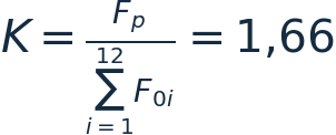
The abrupt change in flow area from the feed pipe, Fₚ = 0.083 m², to the combined area of the 12 passages gives the following contraction ratio.
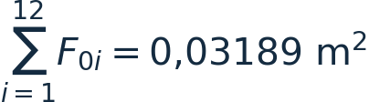
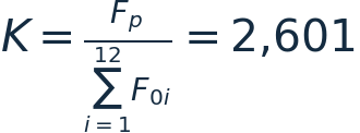
When the gas mixture enters a sharp-edged passage, inertia causes it to separate from the wall near the inlet. The separation and resulting vortices reduce the cross section of the jet. For a straight passage with sharp inlet edges, the area contraction coefficient is given by
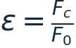
where Fс is the cross-sectional area of the jet and F₀ is the cross-sectional area of the passage. At Re > 10⁴, the area contraction coefficient ε is 0.5. The flow resistance coefficient reaches ζ = 0.5 [3].
Zones of flow separation and an abrupt contraction at 180° cause an unstable turbulent discharge of the gas mixture from the swirlers. The velocity profile across the swirler is sawtoothed.
The reference burner therefore has high flow resistance and a pulsating, unsteady turbulent flow at the swirler outlets. The journal denotes this flow regime by Re ∼ Var. It destabilizes combustion of the mixture and reduces acetylene output.
2. The reference burner lasts only 720–2160 h because the stabilizing-oxygen tubes fail at the welds joining them to the bottom plate. The tube failure is associated with stress concentration in the fracture zone due to unequal thermal elongation of the swirlers and oxygen tubes. The difference in thermal elongation results from the different lengths of the components, which the article says is confirmed by the strength calculation. In service, the welds fail because the swirlers and tubes undergo different amounts of thermal elongation.
Calculation of thermal elongation and stress
| Input data | In swirlers | In the jacket | In tubes |
|---|---|---|---|
| Working fluid temperature, °C | 650 | 35–60 | 30 |
| Working fluid | CH₄ + O₂ | H₂O | O₂ |
| Material | 12Х18Н10Т | ХН32Т | ХН32Т |
To calculate the stresses around the weld, we assume that the frame consisting of the upper and lower plates and the shell is rigid. Table 2 lists the terms, symbols and mechanical properties of alloy KhN32T used in the calculation [4].
| Input data | Value |
|---|---|
| Young’s modulus at design temperature | E = 2,05 · 10⁵ MPa |
| Linear expansion coefficient at design temperature | K = 18,6 · 10⁻⁶ °C⁻¹ |
| Ultimate strength at design temperature | K = 18,6 · 10⁻⁶ °C⁻¹ |
| Swirler length | L₁ = 0,166 m |
| Tube length | L₂ = 0,079 m |
| Assembly temperature | t꜀ = 20 °C |
| Design temperature | tₚ = 650 °C |
1. Thermal elongation of the swirlers

2. Thermal elongation of the stabilizing-oxygen supply tubes

3. Difference in thermal elongation

In practice, the burner structure deforms under load. The measured deflection of the lower plate and stabilizing-oxygen manifold is 0.87 mm = 0.00087 m. Allowing for that deflection, the difference in thermal elongation is

The journal gives the stress induced in the tubes and weld by thermal deformation as follows.

The journal gives a stress of 404.7 MPa. The author concludes that the stress exceeds the ultimate strength of the welded joint and causes the burner to fail [5, 6].
Design objective and technical results
The invention aims to improve the acetylene burner. The design changes include the shape of the overall gas-distribution block and its upper part, the passages supplying the gas mixture and stabilizing oxygen, the stabilizing-oxygen manifold and the way these elements fit together. According to the author, the proposed design achieves the following results.
• It increases the combined cross-sectional area of the gas passages from 0.03189 to 0.050 m², lowers the contraction ratio from 2.601 to 1.66 and reduces losses of the initial kinetic energy of the gas flow.
• It reduces the flow resistance coefficient from 0.50 to 0.12, a factor of 4.17.
• It eliminates the thermal stresses that cause the oxygen-supply tubes to fail in the reference burner and the earlier burner [1], rendering them inoperable.
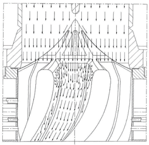
• It provides steady turbulent gas flow in the passages, denoted in the article by Re = const. Across each passage, the velocity increases monotonically from the wall to the flow axis.
• It stabilizes combustion of the gas mixture.
• It increases the burner’s acetylene output.
• It substantially extends burner service life by eliminating the mechanism that causes the thermal stresses described above. Using a single gas-distribution block and replacing the oxygen tubes with drilled and bored passages removes the differences in length between separate components subject to thermal elongation. This eliminates the source of the stresses that cause the oxygen tubes to fail in the two burners described above.
Proposed burner and gas-dynamic calculation
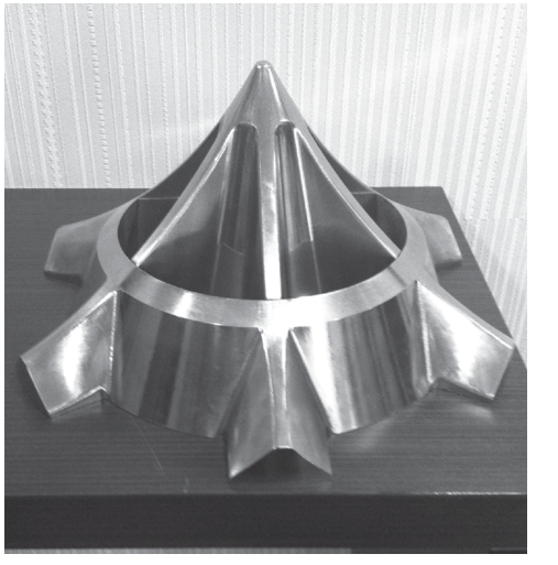
The burner for the thermo-oxidative pyrolysis of methane has a block-type gas distributor with passages for the gas mixture and for stabilizing oxygen, the latter connected to an oxygen manifold. The proposed design meets the objective by changing the gas distributor. A single block guides and distributes the flow. The passages for the mixture and stabilizing oxygen and the oxygen manifold are milled directly into the monoblock. The upper part of the block is a cone with a cycloidal generatrix, which the article calls a brachistochrone. The inlets to the gas passages contract gradually from one trapezoidal cross section to another at an angle α = 40–60°.
The technical result of the invention is a substantial increase in burner service life and output.
The proposed burner is a monoblock that simultaneously guides and distributes the gas mixture and stabilizing oxygen through separate passages into the reaction and combustion zones.
The passages supplying the gas mixture and stabilizing oxygen are milled into the monoblock itself. The stabilizing-oxygen passages connect to an oxygen manifold also milled into the same block.
To reduce drag on the gas flow, the upper part of the monoblock is a cone with a cycloidal generatrix. The profile is constructed by calculating points on the cycloid and interpolating at 0.01 mm intervals along the X axis. This gives a smooth curve with low drag.
The gradually contracting passage inlets retain a trapezoidal cross section. The contraction angle is 40–60°. The combined flow area of the passages increases from 0.03189 to 0.050 m².
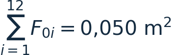
The cross-sectional area of the feed pipe remains the same as in the reference burner, Fₚ = 0.083 m². The contraction ratio decreases from 2.601 to 1.66.
The contracting portion of the passage is a smooth collector whose contour follows an arc of a lemniscate. Together with the chosen contraction angle, this profile substantially reduces the flow resistance coefficient. The journal gives the following integral formula for the proposed design.
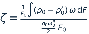
In the description of the formula, ρ₀ and ρ′₀ denote the total pressures upstream and downstream of the collector. The symbol ω₀ denotes the velocity in the feed pipe, ω the velocity in the gas passage, and F₀ the passage cross-sectional area.
Solving the equation for this design, the author obtained a flow resistance coefficient of ζ = 0.12, a reduction by a factor of 4.17 compared with the reference burner. Fig. 6 shows steady turbulent flow in the gas passages. The velocity profile across each passage increases monotonically from the wall to the flow axis.
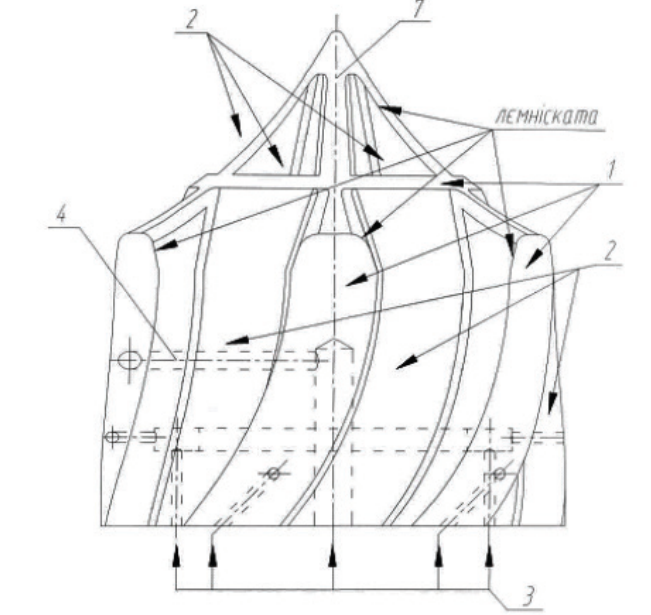
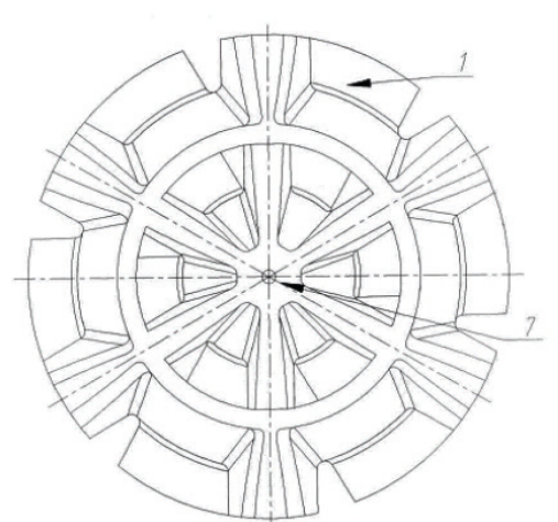
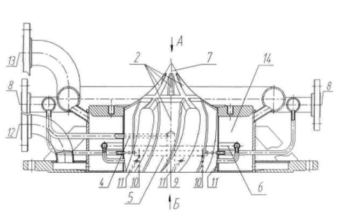
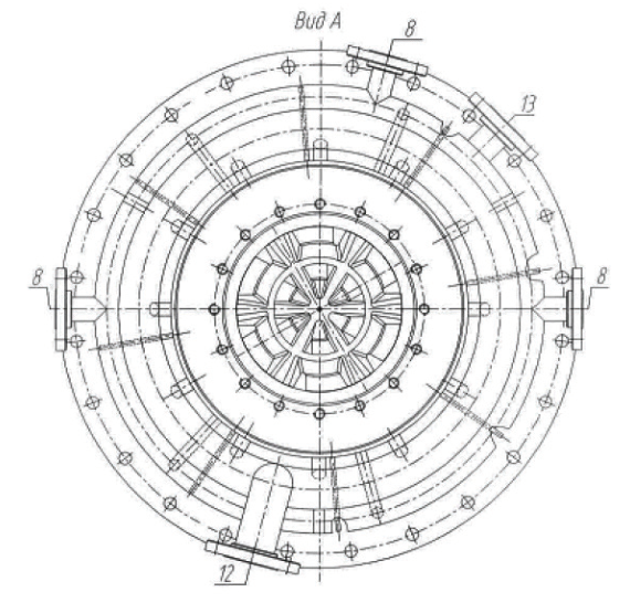
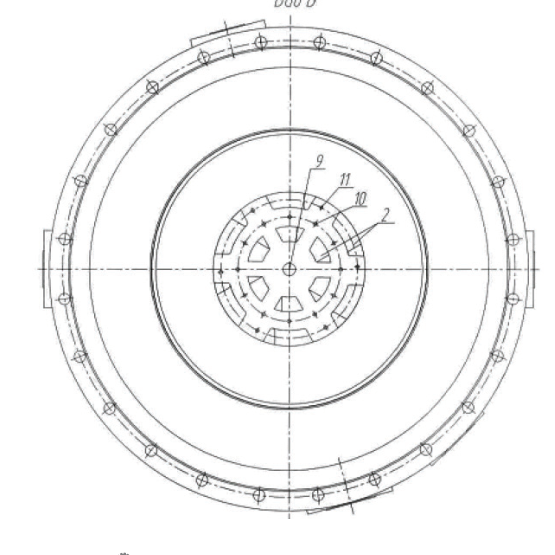
The drawings in Figs. 1–6 illustrate the proposed design. Figs. 1 and 2 show front and top views of the burner. Fig. 3 shows a longitudinal section through the burner in its water-cooling jacket, with the stabilizing-oxygen supply pipes connected. Fig. 4 shows view A from above in Fig. 3, and Fig. 5 shows view B from below in Fig. 3. Fig. 6 shows the gas mixture flow pattern inside the burner.
Burner components and operation
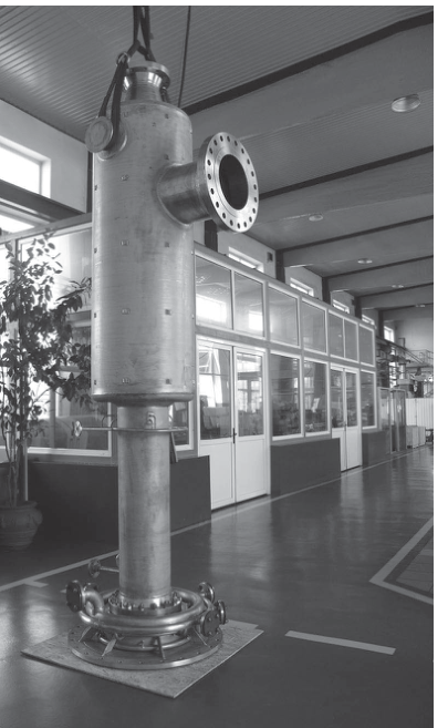
Fig. 7 shows the burner assembled with the mixer. Fig. 8 shows the burner nozzle monoblock.
The burner shown in Figs. 1–6 comprises the following components.
• Gas-distribution monoblock 1, which guides and distributes the gas mixture and stabilizing oxygen through separate passages into the reaction and combustion zones.
• Gas-mixture passages 2 and stabilizing-oxygen passages 3, milled directly into monoblock 1.
• A stabilizing-oxygen supply manifold milled into the block, with three sections, central section 4, inner section 5 and outer section 6.
The upper part 7 of gas-distribution monoblock 1 is a cone with a cycloidal generatrix (Figs. 1–3). The inlets to gas passages 2 gradually contract, with a trapezoidal cross section and a contraction angle α = 40–60°. The oxygen passages 3 include a central passage and straight and inclined passages (Figs. 1, 3).
Figs. 3–6 also show the following components.
• Inlet 8 for stabilizing oxygen to central manifold 4, inner manifold 5 and outer manifold 6.
• Outlet 9 for stabilizing oxygen from central passage 3.
• Outlet 10 for stabilizing oxygen from the straight passages 3 of the inner manifold.
• Outlet 11 for stabilizing oxygen from the inclined passages.
• Inlet 12 for softened water used to cool the burner.
• Outlet 13 for softened water after cooling the burner.
Gas-distribution monoblock 1 sits inside water-cooling jacket 14. Before operation, softened water is supplied to jacket 14.
In operation, the methane–oxygen mixture is supplied to passages 2. Stabilizing oxygen is supplied to passages 3 through central manifold 4, inner manifold 5 and outer manifold 6. The mixture and the stabilizing oxygen flow through their respective passages into the reaction and combustion zones. Acetylene and the other combustion products from the reaction zone are sent to the acetylene recovery system.
References
1. USSR Inventor’s Certificate No. 488793. IPC C07C 11/24, C07C 3/28, F23D 13/40. Published 25 February 1976.
2. USSR Inventor’s Certificate No. 292364. IPC B01J 1/00. Reference design. Date listed in the journal 8 June 1978.
3. Idelchik, I. E. Handbook of Hydraulic Resistance. Moscow, Mashinostroenie, 1992. Chapter 3-1-3, p. 114.
4. Zubchenko, A. S. Handbook of Steel and Alloy Grades. Moscow, Mashinostroenie, 2003.
5. GOST 5632-7. High-alloy corrosion-resistant, heat-resistant and creep-resistant steels and alloys. Grades.
6. GOST R 52857.1-2007. Vessels and apparatus. Standards and methods of strength calculation. General requirements.
Drawings and photographs